Table of Contents
Boost Solenoid Installation
On this page, we cover the typical installation configurations for an electronic boost control solenoid. There are other ways and other solenoids, but we're going to focus specifically on what we've actually tested to work. This includes the Ingersoll-Rand 3-port solenoid and the factory boost control solenoid.
Wiring
 The first thing you'll need to do is to wire the sensor into your harness.
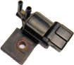
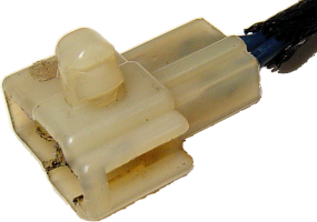
To do that, locate the factory BCS connector under your hood. It will be located near the passenger side headlight area and will look like the connector to the right.
If you are installing a stock boost control solenoid, then this step is pretty easy…just plug the solenoid into the stock harness.
If you are installing an aftermarket solenoid, then you'll need cut the factory connector off the harness and hardwire (solder and heatshrink) your solenoid into place. Wire color and which wire goes where doesn't matter here. One side is +12v, the other is a switch to ground from the ECU. It doesn't matter which goes where on the replacement solenoid.
Pigtail
 Alternatively, you can wire up a pigtail if you'd like.
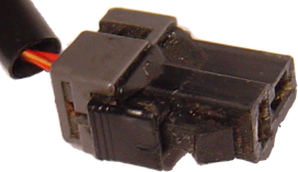
Because we have to test several different solenoids and have to maintain the ability to test other solenoids in the future, we have a small pigtail made up using a connector found randomly on the 2G wiring harness.
A picture of this connector is to the right. That plugs directly into factory boost control solenoid connector shown above.
On the other end of this pigtail, we have a generic connector that we then use for all our other solenoid pigtails so we can swap different solenoids in and out at any time.
Basic 3-port Operation
The following is a diagram of the basic 3-port solenoid air valve. One port will be “common” to the other two ports. When the solenoid is activated (energized, turned on, whatever), one port will be “connected” to the common port. When the solenoid is deactivated, the other port will be connected to the common port.
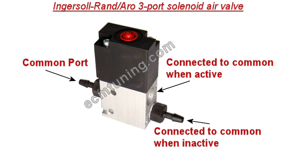
The typical installation will involve routing the hoses so that pressure is applied to your wastegate actuator (which opens the wastegate and reduces boost) when the solenoid is deactivated. This provides some safe guard against a solenoid failing in a deactivated state (typical failure state) or becoming electrically disconnected. In either of those failures, you would simply end up with wastegate pressure (typically around 10-15psi) as your resulting boost pressure.
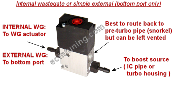
Typical 3-port Internal or Simple External Setup
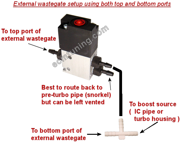
Typical External Setup Using Both Bottom and Top Ports
Stock Setup - Using Stock 2-Port Solenoid
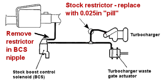
The basic stock 2-port setup is illustrated below. The “pill” is just an in-line restrictor with a defined opening of some size. Our testing indicates that an opening of roughly 0.025“ is sufficient for normal operation.
We do not have a definite source for these pills, but if you search around for "evo lancer boost control pill", you'll find what you need. It has also been suggested to use 0.025” welding tips for this purpose. Again, we have no experience with this idea, but it seems plausible.
Page Tools
